Serial Electrical Interfaces
RS-232
Quite possibly the most widely used communication standard is RS-232. This implementation has been defined and revised several times and is often referred to as RS-232 or EIA/TIA-232. It is defined by the EIA as the Interface between Data Terminal Equipment and Data Circuit-Terminating Equipment Employing Serial Binary Data Interchange. The mechanical implementation of RS-232 is on a 25-pin D-sub connector. RS-232 is capable of operating at data rates up to 20K bps at distances less than 50 feet. The absolute maximum data rate may vary due to line conditions and cable lengths. RS-232 often operates at 38.4K bps over very short distances. The voltage levels defined by RS-232 range from -12 to +12 volts. RS-232 is a single-ended or unbalanced interface, meaning that a single electrical signal is compared to a common signal (ground) to determine binary logic states. A voltage of +12 volts (usually +3 to +10 volts) represents a binary 0 (space) and -12 volts (-3 to -10 volts) denotes a binary 1 (mark). The RS-232 and the EIA/TIA-574 specifications define two types of interface circuits, Data Terminal Equipment (DTE) and Data Circuit-Terminating Equipment (DCE). Sealevel adapters provide a DTE interface.
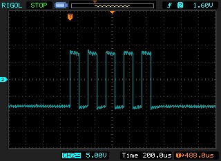
The following is an oscilloscope shot of the capital letter “U” being transmitted at 9600 bps by a Sealevel USB serial adapter. Since there is only 5 volts available to the USB device, we use a ‘charge pump’ transceiver, which provides about -8 volts for a mark and +8 volts for a space.
RS-422
The RS-422 specification defines the electrical characteristics of balanced voltage digital interface circuits. RS-422 is a differential interface that defines voltage levels and driver/receiver electrical specifications. On a differential interface, logic levels are defined by the difference in voltage between a pair of outputs or inputs. In contrast, a single-ended interface, for example RS-232, defines the logic levels as the difference in voltage between a single signal and a common ground connection. Differential interfaces are typically more immune to noise or voltage spikes that may occur on the communication lines. Differential interfaces also have greater drive capabilities that allow for longer cable lengths. RS-422 is rated up to 10 Megabits per second and can have cabling up to 4000 feet long. RS-422 also defines driver and receiver electrical characteristics that will allow one driver and up to 32 receivers on the line at once. RS-422 signal levels range from 0 to +5 volts. RS-422 does not define a physical connector.
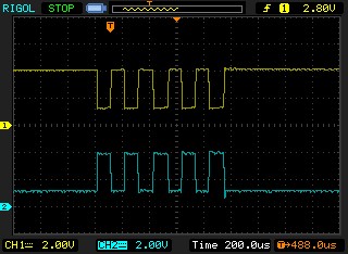
The following is an oscilloscope shot of the capital letter ‘U’ being transmitted at 9600 bps by a Sealevel USB serial adapter. The trace labelel ‘1’ is the data(+) line which is at +4 volts when in the mark condition and +1 volts in the space condition. Since this is a balanced or differential signaling interface, the trace labeled ‘2’ is at +1 volt in the mark condition and +4 volts in the space condition.
RS-485
RS-485 is backwards compatible with RS-422; however, it is optimized for party-line or multi-drop applications. The output of the RS-422/485 driver is capable of being Active (enabled) or Tri-State (disabled). This capability allows multiple ports to be connected in a multi-drop bus and selectively polled. RS-485 allows cable lengths up to 4000 feet and data rates up to 10 Megabits per second. The signal levels for RS-485 are the same as those defined by RS-422. RS-485 has electrical characteristics that allow for 32 drivers and 32 receivers to be connected to one line. This interface is ideal for multi-drop or network environments. RS-485 tri-state driver (not dual state) will allow the electrical presence of the driver to be removed from the line. Only one driver may be active at a time and the other driver(s) must be tri-stated. RS-485 can be cabled in two ways, two-wire and four-wire mode. Two-wire mode does not allow for full duplex communication and requires that data be transferred in only one direction at a time. For half duplex operation, the two transmit pins should be connected to the two receive pins (Tx+ to Rx+ and Tx to Rx ). Four-wire mode allows full duplex data transfers. RS-485 does not define a connector pin out or a set of modem control signals. RS-485 does not define a physical connector.
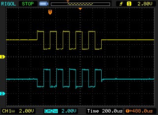
The following is an oscilloscope shot of the capital letter ‘U’ being transmitted at 9600 bps by a Sealevel USB serial adapter. The trace labeled ‘1’ is the data(+) line which is approximately +2.5 volts when tri-stated. Once transmission is started, the line is driven to +4 volts when in the mark condition and +1 volt in the space condition. Since this is a balanced or differential signaling interface, the trace labeled ‘2’ is at approximately +2.5 volts when tri-stated. When transmission is started, it is driven to +1 volt in the mark condition and +4 volts in the space condition. In a properly terminated system you would have a 1K ohm pull-up resistor on the (+) line to +5 volts, a 120 ohm terminating resistor between the (+) and (-) lines, and a 1K ohm pull down resistor to ground on the (-) line. This would give the (+) line a tri-stated voltage of 2.6415 volts. The (-) line would then have the tri-stated voltage of 2.3585. Therefore, the difference would be 0.283 volts which is enough to keep the signals for being misinterpreted as noise.
RS-530, RS-530A
RS-530 (a.k.a. EIA-530) compatibility means that RS-422 signal levels are met and the pin out for the DB-25 connector is specified. The EIA (Electronic Industry Association) created the RS-530 specification to detail the pin out and define a full set of modem control signals that can be used for regulating flow control and line status. The major difference between RS-530 and RS-530A lies in some of the modem control interface signals. In RS-530 the signals all of the modem control signals are differential; in RS-530A some of these signals are single-ended. The RS-530 specification defines two types of interface circuits, Data Terminal Equipment (DTE) and Data Circuit-Terminating Equipment (DCE). Sealevel adapters provide a DTE interface.
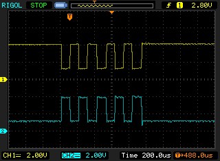
Since RS-530 is RS-422 with a defined pin out, the oscilloscope traces are identical. The following is an oscilloscope shot of the capital letter ‘U’ being transmitted at 9600 bps by a Sealevel USB serial adapter. The trace labeled ‘1’ is the data(+) line which is at +4 volts when in the mark condition and +1 volts in the space condition. Since this is a balanced or differential signaling interface, the trace labeled ‘2’ is at +1 volt in the mark condition and +4 volts in the space condition.
V.35
V.35 is a standard defined by ITU (formerly CCITT) that specifies an electrical, mechanical, and physical interface that is used extensively by high-speed digital carriers such as AT&T Dataphone Digital Service (DDS). ITU V.35 is an international standard that is often referred to as Data Transmission at 48K bps Using 60-108K Hz Group-Band Circuits. ITU V.35 electrical characteristics are a combination of unbalanced voltage and balanced current mode signals. Data and clock signals are balanced current mode circuits. These circuits typically have voltage levels from 0.5 Volts to -0.5 Volts (1 Volt differential). The modem control signals are unbalanced signals and are compatible with RS-232. The physical connector is a 34-pin connector that supports 24 data, clock and control signals. The physical connector is defined in the ISO-2593 standard. ITU V.35 specification defines two types of interface circuits, Data Terminal Equipment (DTE) and Data Circuit-Terminating Equipment (DCE). Sealevel adapters provide a DTE interface.
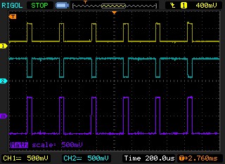
In V.35 mode, trace 1 shows a swing from about 100 millivolts to 700 millivolts. Trace 2 shows a swing from 700 millivolts to 100 millivolts. The trace labeled ‘m’ is signal 1 minus signal 2 and shows a swing from -500 millivolts to +500 millivolts giving a 1 volt differential swing.
Categories:
