How To Construct Serial Loopback Adapter Plugs
Sealevel serial I/O devices typically include a loopback plug with each shipment that can be used to test data lines. Additional loopback plugs can be purchased for a small charge. Item number LB101 is a DB-9 loopback that is specially constructed to test data signals on RS-232 and Sealevel RS-422, RS-485 serial ports. Item number LB102 is a DB-25 loopback that is used to test RS-232 serial ports. Please contact your sales representative for more information.
If you want to test modem control signals or you need to construct your own loopback, follow the instructions below. Use the diagram appropriate to your electrical interface.
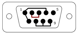
DB-9 RS-232 Loopback Connection (TIA-574)
Connect Pins:
- 2 to 3 (Rx to Tx)
- 1 to 4 to 6 (DCD to DTR to DSR)
- 7 to 8 to 9 (RTS to CTS to RI)
Pins marked in red are the data lines, Tx and Rx, and are necessary for the loopback and BERT testing. All other pins are for modem control signal tests and are not necessary to connect unless you wish to test those signals.

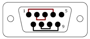
DB-9 RS-422, RS-485 Loopback Connection (Sealevel Product Specific)
Connect Pins:
- 1 to 4 (Rx+ to Tx+)
- 2 to 3 (Rx- to Tx-)
- 6 to 9 (RTS+ to CTS+)
- 7 to 8 (RTS- to CTS-)
Pins marked in red are the data lines, Tx and Rx, and are necessary for the loopback and BERT testing. All other pins are for modem control signal tests and are not necessary to connect unless you wish to test those signals.

DB-25 RS-232 Loopback Connection (EIA-232)
Connect Pins:
- 2 to 3 (Tx to Rx)
- 4 to 5 to 22 (RTS to CTS to RI)
- 6 to 8 to 20 (DSR to DCD to DTR)
Pins marked in red are the data lines, Tx and Rx, and are necessary for the loopback and BERT testing. All other pins are for modem control signal tests and are not necessary to connect unless you wish to test those signals.

DB-25 RS-422, RS-485, RS-530 Loopback Connection
Connect Pins:
- 2 to 3 (Tx- to Rx-)
- 14 to 16 (Tx+ to Rx+)
- 5 to 4 (RTS- to CTS-)
- 13 to 19 (RTS+ to CTS+)
- 10 to 22 to 23 (DCD+ to DSR+ to DTR+)
- 6 to 8 to 20 (DCD- to DSR- to DTR-)
Pins marked in red are the data lines, Tx and Rx, and are necessary for the loopback and BERT testing. All other pins are for modem control signal tests and are not necessary to connect unless you wish to test those signals.

Categories:
